The hidden proportions in the trait of the trompe of Anet
Camillo Trevisan
email: trevisan@iuav.it
Istituto
Universitario di Architettura di Venezia
Dipartimento di Progettazione Architettonica
This paper was published in
Disegnare idee e immagini, n. 16 (1999)
October 1999
Best view with Internet Explorer.
Philippe
de La Hire gives the simplest explanation of the meaning of the term trait:
“The workers call the science of the trait, when cutting the stone,
the science that teaches how to cut and separately construct more than
one ashlar of stone so that, when they are put together (at the right
moment), they create a piece of handwork that can be considered as a
single object.” [1]
The
trait is therefore a diagram, usually drawn to scale, which
allows us to solve real constructive problems connected to the
structure and the cut of the ashlars of stone. [2]
One
of the first writers in this field was Philibert Delorme [3], who shows, amongst other
things, the modality of the definition of the trait [4]
relative to the trompe of Anet [5]
(figures 1-5).
This
small cabinet – made around the middle of the sixteenth
century in the Castle of Diane de Poitiers and which is now destroyed
– was used by successive writers as a paradigm and complex and
daring model of construction.
The
geometrical method of the trait developed by Delorme, which
seems to be muddled and unclear, is actually a very simple application
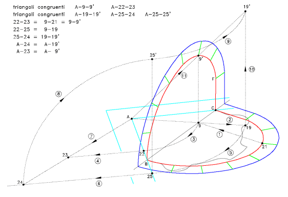
(figure 6). By means of rotation and overturning, starting from a plan
and a vertical section, it is possible to define the height of each
point of the construction and therefore the curve of intersection
between the two surfaces in the two dimensions of the diagram.
Furthermore, still following the same procedure, it is possible to
construct the development boards (panneaux) of the
inferior and superior surface of the vault and its front. In this way
not only can development boards or plaster models be easily
constructed but it is also possible to proceed operatively with the
cutting of the stone ashlars.
In fact, two principal procedures may be used for the cutting: par équarrissement
and par panneaux or direct method.
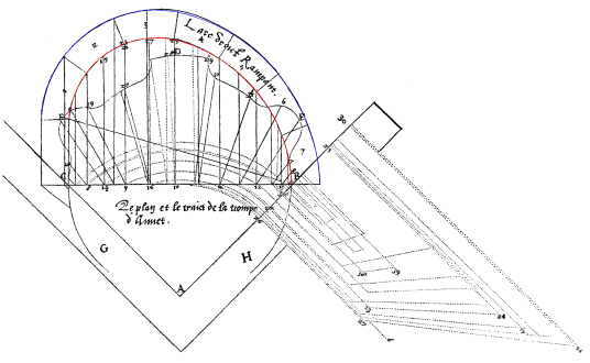
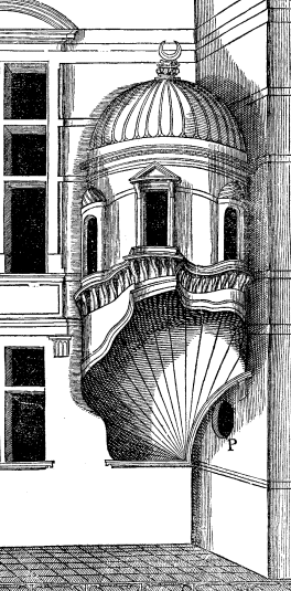
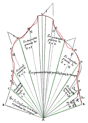
Figure 2. Delorme, op. cit., f. 92v-93r. Trait used for the construction of the development boards of the trompe of Anet. The ovals obtained by means of the construction presented in the article are highlighted to facilitate comparison.
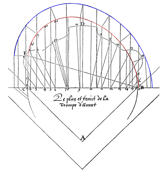
Figure 3. Delorme, op. cit., f. 96v. Trait used for the construction of the development boards of the trompe of Anet. The ovals obtained by means of the construction presented in the article are highlighted to allow comparison. In the Delorme treatise all diagrams are to the same scale.
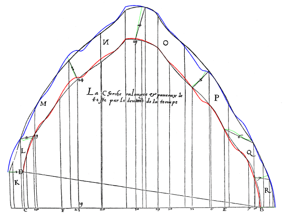
Figure 4. Delorme, op. cit., f. 95v. Development board of the inferior vault of the trompe of Anet. The ovals obtained through the use of the software TROMPE are highlighted to facilitate comparison (the use of the software is free and it is found on the web-site trompe.htm, and enables the production of a three dimensional face model and the development boards of a generic conic trompe, starting from the trait).
Figure 5. Delorme, op. cit., f. 94v. Development board of the frontal face of the trompe of Anet. The constructions obtained through use of the software TROMPE are in colour to facilitate comparison. As in the preceding image, the superimposition at the points which Delorme certainly calculated should be noted.
In the first case,
which goes back a very long time, orthogonal projections of the ashlar
are used which are normally of a very simple shape. Once a
parallelepiped of stone that contains the complete ashlar has been
squared, one continues to work along the perpendicular direction to
the face of the block, following the projections which are on the face
itself.
On the other
hand, following the par panneaux method, each face of the
ashlar is obtained from another which is adjacent to it, knowing the
angle between the two faces and, in the case of curve surface, the
mould that defines the curvature. [6]
The
method is generally applied to the morphologically more complex
ashlars – as in the case of the trompe of Anet – but
requires an accurate calculation of the angles and the shape of the
panels since possible errors would accumulate with each phase of
cutting.
The methods of stereotomy – like for example, those of graphic static
– require absolute coherence
between the design phase and the actual execution. The trait can in no way be a simple
declaration of intention: in essence purely ideological and with the
possibility of ample correction during the course of the work.
Rather, the most minimal displacement of the smallest segment
would reverberate on the building greatly amplified with repercussions
that could be, in some cases, critical also regarding its stability.
Here
attention is focused on the research of the proportions between the
graphic elements of the principle trait. Indeed, this latter
represents a vertical section of the piece and therefore completely
defines the relationship between the components.
The search for the proportions in the diagram is therefore equivalent
to a proportional study of the structure itself: in this case, an
analysis which is no longer possible. Nevertheless, considering the
intention of Delorme himself when he said he would write a Second
Tome de l’Architecture entirely dedicated to the study of
proportions [7],
this research does not seem impertinent.
The trait of the trompe of Anet
The
research that has been carried out can be divided into several
essential steps:
· the
identification of the geometrical shape of the overturned vertical
section to define whether it is oval or elliptic;
·
study
of the geometrical proportions which are referred to as trait;
·
confirmation
of the reciprocal coherence of the diagrams presented in Delorme’s
work;
·
definition
of the size of the piece and of the scale of the diagrams based on
available documentation.
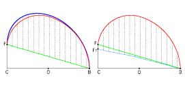
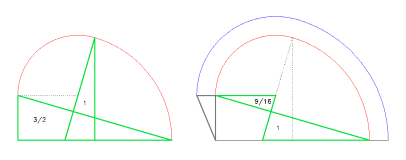
Robin Evans suggests that the main curve of the trait is an asymmetrical semi-ellipse which is generated by letting the vertical chords of a semi-circle slide, constructed on the base, to the point at which they intersect with the inclined line: the ramp of the trompe (figure 7) [8]. However, this procedure, even if ingenious and elegant (also illustrated by De La Rue [9]), does not however produce the curve shown in the trait of the trompe of Anet and neither does it produce a true ellipse.
Figure 7. Analysis of the hypothesis of construction of a curve obtained by following the method proposed by Robin Evans. Look at the base segment BD and the height CF (diagram on the left), starting from BF segments rise perpendicular to CB, an equal length to their vertical distance from BF. However, with this construction we get a curve (the superior one) that does not coincide at all with the one used by Delorme as section profile. The curve that was actually used (diagram on the right), following the same procedure but backwards, leads to the line BF1 (which is really a broken line very close to a straight line). As can be seen, the difference is not small and is definitely greater than the error made by the engraver.
Figure 8. Construction of the rampant arch proposed by De La Rue. Once the base AB, the ramp AD and a vertical segment from the average point of AB have been defined, LK is placed the same to LB.. Once the half point E of BK has been identified, point F is found, centre of the arch G from B to K, and successively the point I, centre of the arch H from D to K. In this way the two centres are aligned with the point of junction. In the diagram the same letters are used as by the author.
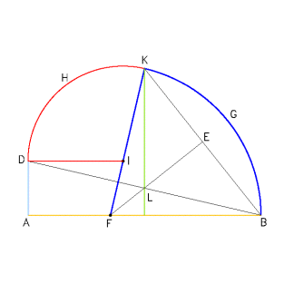
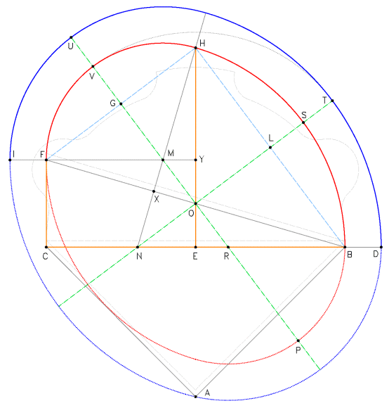
Figure 9. Construction of the internal and external ovals. The two starting point segments are CB, equal to 7.2 feet and EH, equal to 2/3 of CB, 4.8 feet. The triangles EHB and FYH are perfect right-angled triangles 3-4-5. The minor semi-axis of the external oval is congruent to the major semi-axis of the internal oval. The plan of the trompe is shown in by the dotted line in grey, translated by 1/6 foot with respect to the original base CB.
Figure 10. Diagram showing the number of ratios established between the principle segments of the trait with the variation of the ratio between the base and the height of the internal oval. The oval under examination in the article refers to a ratio between base and height equal to 1.5 (EH = 2/3 CB).
De
La Rue himself [10],
however, discusses another method to construct a rampant arch, in this
case an oval (figure 8). Such a procedure, which is extremely simple,
also foresees the alignment with the points of connection between the
two circle arches thus guaranteeing the static of the construction.
Supposing the generating curve is an oval rather than an ellipse also
takes into consideration the ease with which an oval can be
constructed and, above all, of the ashlars with a circular sectioned
rather than elliptical surface; and
finally, of similar examples relating to the rampant arch.
However, since the difference existing between an ellipse and an oval
is minimal (the maximum distance between the two curves is, in this
case, less than 0.4% of the major axis), these arguments, however
solid, are not sufficient to unequivocally define the shape of the
curve. Ulterior decisive evidence is necessary that is not based only
on the direct comparison – neither conclusive nor univocal – but
also based on theoretical, geometrical and mathematical verifications;
in short, based on proportions.
The geometrical shape of the vertical section
The
segments on which the construction of the trompe is based are
obviously the base, the height of the vault at the mean point and the
height of the ramp (segments BC, EH and CF in figure 9). The base
determines the area of the plan and also the length the supporting sides which converge in vertex A; the second
segment defines the height of the vault; the third, linked to the
first two, shows how rampant the vault will be. [11]
They therefore define the limits of the figure of construction and
therefore the shape of the inferior surfaces, the intrados of the
rampant vault. [12]
The method illustrated by De La Rue (figure 8) produces infinite ovals
which are all different to one another and all characterized –
regardless of the ratio between base and height – by numerous
geometrical, arithmetical and harmonic proportions recurring amongst
the constructive segments. They are all exact, that is with a
deviation amongst the ratios or differences that is equal to zero (cf.
tables 2, 3, 4).
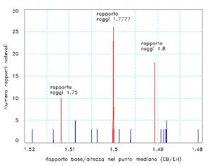

Amongst
the infinite ovals with an identical or almost identical geometry to
the one described by Delorme there is only one, however, that stands
out due to its distinctive characteristics (figures 9 and 10). [13]
It is the oval based on perfect right-angled triangles [14], mainly on the triangle
3-4-5. [15]
Once the base BC has been defined (figure 9) and the mid-way point E
has been found, a first triangle 3-4-5 with its shorter cathetus equal
to EB, half of the base is formed. The longer cathetus EH is therefore
equal to 4/3 of EB or also 2/3 of BC. A second triangle 3-4-5 will
have a longer cathetus which is as long as EB and a vertex in H
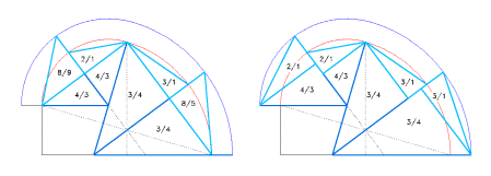
(figure 11.1).
This simple operation completely defines the internal oval, finding
the ramp CF by difference; simultaneously constructing a rich series
of similar triangles (figure 11).
The external oval (the extrados of the vault) can easily be found by
making the length of its minor semi-axis equal to that of the major
semi-axis of the internal oval. [16]
There are other right-angled triangles defined in the trait
which are singular (BCF, NEH, NXB and MXF in figure 9). In fact, the
lengths of the sides of these triangles for a Pythagorean triplet with
a proportional sequence of 7-24-25. Circularly, the four triangles
define the fundamental links that exist between the base and ramp;
between the longer radius and height and between the two radii of the
oval and the base itself (figure 12).
Finally, the triangle CFI – in turn derived from the ramp and from
the difference of the semi-axis of the oval – is still a perfect
right-angled triangle with a proportional sequence of 5-12-13 (figure
12.2).
In this constructive diagram the first three perfect right-angled
triangles are therefore all present and closely linked to one another
in a dense intertwining of relationships and proportions.
A pattern that is anything but accidental, above all if one considers
the complete superimposition of the two ovals with both examples
studied so far [17],
even with the slight imperfections of a xylograph (figures 2 and 3).
As further evidence the triangles 3-4-5 – placed with their
hypotenuse on the radii of the internal and external ovals – are in
close relationship to the corresponding right-angled triangles, with
one cathetus in common and the other that completes the lengths of the
semi-axis (figure 13). The
cathetus of these last triangles are in a relationship of 2/1 for the
major semi-axis and of 3/1 for the minor semi-axis.
Figure 11. Identification in blue of some perfect right-angled triangles characterized by the ratio of the sides of 3-4-5. The radius of the inscribed circle, indicated by the bigger triangles, is equal to a third of the shorter side of the triangle. The sequence of ratios that connect the sides of the various triangles and the latter to the fundamental segments of the trait and other perfect triangles with the ratios 7-24-25 and 5-12-13 should be noted.
Figure 12. Identification of some perfect right-angled triangles with a ratio of the sides of 7-24-25 (in green) and 5-12-13 (grey). As in the case of the triangles 3-4-5 the sequence of the ratios that connect the sides of the various triangles and the latter with the fundamental segments of the trait should be noted.
Figure 13. Existing ratio between the triangles 3-4-5, with their hypotenuse on the radii of the internal and external ovals and the segments that complete the semi-axis of the internal and external ovals.
That
geometrical figure is therefore not an ellipse since the oval in
question is evidently too full of relationships and proportions to be
ignored; even if an ellipse – without, however, such
strong characteristics – would interpolate it with minimal
deviation.
In particular, apart from the co-relations stemming directly from the
perfect right-angled triangles, the numerous arithmetical proportions
and harmonic characteristics of only that pair of ovals are of
considerable interest (cf. tables 3 and 4).
Definition of the dimensions of the trompe and of the diagram’s scale
Once the geometrical
shape of the figure has
been classified as an oval, the method of graphic construction
identified, the centres and the radii of construction defined and the superimposition
of the ovals with the original diagrams verified, it is now of
interest to determine the dimensions
of the construction
and the scale of the diagram.
A drawing,
identified by Anthony Blunt [18],
shows the western façade of the east wing of the Castle of Anet with
an orthogonal projecting view of the trompe from the side which
is not rampant. From that drawing it is possible to calculate the
measurement of the side, equal to approximately 5.2 feet whereas the
height of the rampant vault is approximately 10 feet. [19]
Another piece of evidence comes from Delorme himself: in one piece of
his study he states that the length of the maximum ashlar is 10/12
feet. [20]
These two figures therefore make up the whole, in truth very much
reduced, of the indications we possess to determine the dimensions of
the trompe.
If the base BC is taken as a point of reference the dimensions can
therefore vary between 5.8 feet (for the length of a maximum ashlar of
10 feet) and 7.4 feet (for a side of approximately 5.2 feet). [21]
Nevertheless, if the proportions of the ovals are kept the same (by
this time identified for good) but the scale is varied, lengths are
generated that are different for the fundamental segments of the trait
and different values for the arithmetical and harmonic proportions.
Also in this case, when testing a large number of possible dimensions
of the trompe, one precise value is identified, the one chosen
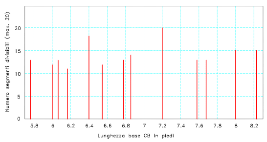
as the real one used for the actual construction (figure 14 table 1). [22]
If the size of the base CB is seven 1/5 feet, the height of the vault
would be exactly 10 feet and the side approximately 5.1 feet, figures
which are in total agreement with the data in our possession. [23]
Figure 14. Diagram showing the number of segments dividable in fractions (calculated using the first twenty natural numbers), varying the scale factor of the oval. For reference, in abscissa the length of the base CB is shown. With sufficient surrounding space, only with a base equal to 7.2 feet can all the fundamental segments of the pair of ovals in question be divided into fractions. The diagram shows only the values of the bases which produce more than 10 segments which can be divided into fractions.
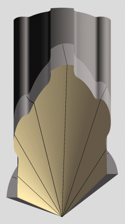
Figure 15. Orthogonal dimetric axonometry of the trompe of Anet. Rendering according to the face three-dimensional model produced by the TROMPE software.
There
remains one more point to be discussed: whether Delorme traced his
diagrams to scale with respect to the building or not.
As far as this is concerned it should be noted that in his study,
Delorme drew the size of the feet and Roman span and French foot
according to natural scale. [24]
Furthermore, apart from shorter variations due to the xylographic
method of printing [25],
the graphics - the two plans, the frontal and intradoxal development
- are all to the same scale: one foot in reality corresponds to 2/3 of
an inch on the drawing (reduction scale 1:18).
This data further confirms and reinforces the hypothesis that proposes
7.2 feet (1 1/5 toise) of size of the constructive base of the whole trait.
Conclusions
The
use of the trait géométrique acts like a design lever on
the building, multiplying the actions in an amazing chain reaction.
Few lines, in this case two simple circle arches regulate and define
the entire architecture, transmitting all the characteristics,
proportions and potential volumes by parthenogenesis.
Indeed, the act of creative planning is found completely in the
construction of the trait: it is an indirect action and it does
not concern the object itself but its constructive sections.
Accordingly, Delorme’s amazement and enthusiasm when he describes
the characteristics and marvelous effects are not hardly surprising.
If we add the immediate possibility of generating three-dimensional
models and of controlling the real construction step by step, the
method of the trait certainly does appear revolutionary novelty.
The most interesting aspect in the study of the proportions of these
diagrams is, perhaps, the attempt itself of being able to try to
verify the primitive stage of the conception of the architecture.
IF 7/8
OM 1 5/16
NE 1 2/5
NO 1 3/4
CF 2 1/10
NM 2 3/16
CN 2 1/5
YH 2 7/10
MH 2 13/16
OS 3 1/4
CE 3 3/5
MU 3 11/16
OV 4 1/8
FH 4 1/2
EH 4 4/5
NH 5
OU 5
NT 5 7/8
HB 6
CB 7 1/5
FB 7 1/2
NO/NH = CF/HB = NO/OU 7/20 0.35
MY/NM = YH/FB 9/25 0.36 (1/2.77777)
MY/CF = YH/CB = MH/FB 3/8 0.375 (1/2.66666)
NE/CE = NO/FH 7/18 0.388888
NM/NH = CF/EH = NM/OU 7/16 0.4375
MY/NO = YH/HB 9/20 0.45 (1/2.22222)
OM/MH = CF/FH 7/15 0.466666
IF/NO = CE/CB 1/2 0.5 (1)
YH/EH = MH/NH = MY/NE = MH/OU 9/16 0.5625 (1/1.77777)
MY/OM = OM/NM = YH/FH = FH/FB = CE/HB 3/5 0.6 (2) (1/1.66666)
MH/FH = FH/CB = OM/CF = IF/NE 5/8 0.625 (1/1.6)
NE/NM = EH/FB 16/25 0.64
OS/NH = OS/OU 13/20 0.65
NE/CF = EH/CB = NH/FB = IF/OM = OU/FB 2/3 0.666666 (3) (1/1.5)
OM/NO = YH/CE = CE/EH = FH/HB 3/4 0.75 (2) (1/1.33333)
CF/YH = NM/MH 7/9 0.777777
NE/NO = NO/NM = CE/FH = EH/HB = HB/FB 4/5 0.8 (2)
NH/HB = HB/CB = NO/CF = OU/HB 5/6 0.833333 (1/1.2)
MY/IF = FH/NH = FH/OU 9/10 0.9 (1/1.11111)
OM/NE = FH/EH 15/16 0.9375 (1/1.06666)
YH/MH = EH/NH = CF/NM = CB/FB = EH/OU 24/25 0.96
OV/OT = NH/OU 1/1 1 (4)
The proportions or ratios which are valid only for the oval in question are in bold. In the other ovals which were constructed using the same method all other proportions are valid but with values which differ to these. The values shown are valid for any scale.
(1) CE=1/2
CB for construction.
(2) Proportions
between the sides of the Pythagorean triangle 3-4-5.
(3) EH=2/3
CB for construction
(4) OV=OT
for construction.
CF-EH = EH-FB -2.7 (216/80, 27/10)
CF-FH = EH-CB -2.4 (192/80, 12/ 5)
OM-CE = WZ-CB = NE-MU -2.2875 (183/80)
NE-CE = NH-CB = OU-CB -2.2 (176/80, 11/ 5)
FH-HB = HB-FB = OM-MH = NO-OS = CF-CE = NM-MU -1.5 (120/80, 3/ 2)
CN-CE = CE-NH = MY-NM = CE-OU -1.4 (112/80, 7/ 5)
IF-CN = NT-CB -1.325 (106/80, 53/40)
MU-NH = IF-NM = MH-OV = CE-WZ = MY-CF = MU-OU -1.3125 (105/80, 21/16)
IF-CF = MU-WZ -1.225 ( 98/80, 49/40)
CE-EH = EH-HB = HB-CB -1.2 ( 96/80, 6/ 5)
MY-NO = WZ-NT -0.9625 ( 77/80)
YH-CE = CE-FH -0.9 ( 72/80, 9/10)
OS-OV=OV-OU=NH-NT = MH-MU = OV-NH = OU-NT = IF-NO = OM-NM -0.875 (1) ( 70/80, 7/ 8)
MH-CE = NE-NM = OM-CF = OV-WZ -0.7875 ( 63/80)
MY-NE = CN-MH -0.6125 ( 49/80)
MY-OM = CE-OV = IF-NE -0.525 ( 42/80, 21/40)
CN-YH = FH-NH = FH-OU -0.5 ( 40/80, 1/ 2)
IF-OM = NO-NM = MU-OV = MH-OS = OS-MU = OM-NO -0.4375 ( 35/80, 7/16)
OS-CE = NE-NO = NO-CF -0.35 ( 28/80, 7/20)
FH-EH = CB-FB -0.3 ( 24/80, 3/10)
YH-MH = EH-WZ -0.1125 ( 9/80)
MY-IF = CE-MU = OM-NE = CF-NM = WZ-NH = WZ-OU -0.0875 ( 7/80)
The
proportions valid only for the oval in question are in bold. In the
other ovals, constructed using the same method but with different
proportions between the base and height all the other arithmetical
proportions are valid, even if they have different values to these.
Furthermore, all the values presented in the table are only valid for
the scale in question (base of 7.2 feet).
There are also the segments MY and WZ (maximum height of the internal
oval at point M and sum of the segments CF and MH).
(1) In
this case, the proportions in bold are also valid for the other ovals,
but each with different values.
IF/NM 2/ 5
IF/CF 5/12
NE/CN 7/11
CF/CE 7/12
NO/OS 7/13
CN/OV 8/15
OV/FH 11/12
OV/HB 11/16
CN/CE 11/18
OV/FB 11/20
OS/FH 13/18
1/NH - 1/HB = 1/HB - 1/FB = 1/OU - 1/HB
0.033333 (3/90, 1/30)
1/CE - 1/FH = 1/FH - 1/HB
0.055555 (5/90, 1/18)
1/CE - 1/EH = 1/EH - 1/CB
0.069444 (5/72)
1/MH - 1/CE = 1/CE - 1/NH = 1/CE - 1/OU 0.077777
(7/90)
1/NE - 1/NM = 1/NM - 1/NH = 1/NM - 1/OU
0.257143 (9/35)
The proportions valid only for the oval in question are in bold. In the other ovals which were constructed using the same method, all the harmonic proportions are valid but with values that differ to these. Furthermore, all the values presented in the table are only valid for the scale in question (base of 7.2 feet).
[1] Philippe de La Hire, Traité de la coupe des pierres, ms. 1596, Bibliothèque de l’Institut de France, Paris, f.1.
[2] On the Internet site: http://www.iuav.it/dpa/ricerche/trevisan/stereo/stereo.htm a study on stereotomy and the technique of the trait can be found. Stereotomy is the science of the cut of solids; it uses geometrical projections to determine the shape and dimensions of the ashlars of stone that make up arches, vaults and cupolas. Therefore, it is not the simple preparation of stone ashlars but rather the combination of the codified, coherent and repeatable geometrical procedures, suitable for planning and representing complete buildings made of stone. Jaques Curabelle used the term stereotomy for the first time in his libel against Desargues in 1644: Examen des oeuvres du Sieur Désargues.
[3] The first edition of Philibert Delorme’s work was published in 1567 (Frédéric Morel, Paris), under the title of Le Premier Tome de l’Architecture… This first edition consisted of nine books. As evidence of its success it was republished in 1576-78, 1626, 1648, 1894 including two additional books, X and XI, the Nouvelles Inventions pour bien bastir et à petits fraiz… (first edition, Frédéric Morel, Paris, 1561). The 1648 edition (David Ferrand, Rouen) was reprinted in an anastatic reproduction in 1981 in Brussels by Pierre Mardaga. The 1567 edition was reprinted anastatically in 1988 together with the Nouvelles Inventions… and with a presentation and comment by Pérouse de Montclos, by the publisher Léonce Laget, Paris.
[4] In his work Delorme uses the term traict rather than trait: the latter will be used here since it was used by successive writers and is used currently.
[5] The trompe is a small vault – usually formed by stone ashlars – which supports a covering or a overhanging wall. Like all vaults or arches the trompe supports itself – and wall works above it – by placing the weight of the entire structure on the imposts. This voute suspendue en l’air, as Delorme himself calls it, was built to support stairs or small cabinets as in the case of the trompe of Anet without the necessity of resting on the floor; perhaps though, it was to give the whole structure a characteristic element.
[6] A third method exists, par demi-équarrissement, which combines the advantages of the other two. In this case the ashlar is cut using both frontal projections and development boards, moulds and angles being defined by the two faces of the ashlar itself.
[7] “Je n'use d'autres mesures sinon des proportions lesquelles j'ay tirées de l'Escriture saincte du vieil testament et (ce que je diray sans aucune jactance) les mets en usage le premier, ainsi que je feray apparoir de bref, Dieu aydant, par le discours de nostre seconde partie d'architecture, qui porte le titre et nom: Des divines Proportions”. Delorme, op. cit., f. 168r.
[8] Robin Evans, La trompe di Anet, in “Eidos”, 2 (1988), pp. 50-57. See figure 7. Once the segment of base BC and the height CF (picture on the left) have been determined, starting from BF perpendicular segments rise to CB, equal in length to their vertical distance from BF. However, as can be seen, a curve (the superior one) is obtained with this construction which does not coincide at all with the one used by Delorme as section profile. The curve used in actual fact (diagram on right), following the same procedure backwards, leads to the line BF1 (in reality a broken line very close to a straight line). If the inclination of the line BF indicated on the trait is used, the curve is too high; or, to obtain a similar curve the inclination itself must be reduced by approximately 3° (BF1), considerably lowering the vertical foot with respect to the original drawing.
[9] Tirer un Arc rampant d’un Arc droit. Jean Baptiste De La Rue, Traité de la coupe des pierres, Imprimerie Royale, Paris 1728, p. 6 tab. I, fig. 9.
[10] Décrire l’Arc rampant de deux ouvertures de Compas. See figure 8. “AD is the height of the ramp, BD the line of the ramp and LK the perpendicular at the half-way point of AB. LK is placed equally to LB take the perpendicular line EF to KB from the half point E of BK. Once point F has been found on AB trace FK and also DI parallel to AB. In this way point I will be found on FK. From point I, and with the radius ID, trace the arc DHK; from point F and with radius FK trace the arc KGB; these two arcs form the desired rampant arc DHKGB”. De La Rue, op. cit., p.6, tab.II, fig.1.
[11] In figure 9 it can be seen that the plan of the trompe has been translated by Delorme by 1/6 of a foot; consequently, the tangents to the two arches at the starting points are not vertical but rather slightly inclined towards the interior. Having cut the lower part of the oval means that the attachment of the vault to the trompe is not at a tangent to the two supporting walls. In this way, not only are the initial angles of the vault visible but above all, by varying the heights the dimensions of the trompe can be adapted to the pre-existing limits: the superseding window on the rampant side and the height of the lofts.
[12] Pérouse de Montclos suggests that Anet’s trompe was spherical, since the description of the trompe in Delorme’s work shows a curved and not rectilinear cut above the window (cf. Jean-Marie Pérouse de Montclos, L’architecture à la française, XVIe, XVIIe, XVIIIe siècles, Picard, Paris 1982, p. 94; see also figure 1). The trait in question and illustrated by Delorme is, however, obviously that of a conic trompe (see also figure 15). Furthermore, Frézier also treats it as a conic trompe when the trompe is still existing (cf. Amédée-François Frézier, La théorie et la pratique de la coupe des pierres et des bois …, 3 vol., Strasbourg-Paris 1737-39, book IV, p.265).
[13] A computer program has been developed which is able to identify the possible ratios between the main segments of the oval by varying the ratio base / height of the oval and considering a ratio amongst the first twenty natural numbers as valid. In figure 10 the results of the analysis of over 40 thousand ovals are shown, with a variable value ranging from 1.52 and 1.48: the oval with a ratio base / height of 1.5 and a ratio amongst the radii of 1.7777… can clearly be seen. It should also be noted that the other two ovals, with a ratio between the radii of 1.75 and 1.8 differ considerably from Delorme’s diagrams in his study, on the contrary to the oval considered to be perfectly coincidental with those diagrams.
[14] The relationship between the three sides L1, L2, L3 of a perfect right-angled triangle are: L1 = q2 - p2; L2 = 2 p q; L3 = q2 + p2; where p and q are two natural numbers, one odd and the other even with a maximum common divider equal to 1. If p = 1 and q = 2 we get a triangle with sides of 3, 4, 5 units; with p = 2 and q = 3 we get a triangle of 5–12–13; while with p = 3 and q = 4 we get the right-angled triangle 7–24–25.
[15] The right-angled triangle with sides that are 3, 4, 5 units long – also known as Pythagoras’ or Plutarch’s sacred triangle – had been used since the Egyptians, also to facilitate the tracing of right angles on the ground using a cord with knots at regular intervals. It is also the only right-angled triangle with sides which are arithmetically proportioned. Matila Ghyka states that this triangle, at the times of the Achemenid and the Sassanid, formed the base for the tracing of vaults with an oval section with a ratio between the axis of 3/4 and between the radii of 3/8 (cf. Ghyka, The geometry of art and life, Sheed and Ward, New York 1946 [reprinted: Dover, New York 1977], p.22).
[16] From the cut of the third ashlar which is aligned with the vertical from the centre of the superior and not the inferior oval base one could deduce that Delorme constructed the external oval before the internal one. Verification, however, immediately eliminates this possibility: above all the two ovals could not be superimposed on the diagrams of Delorme’s work but would also lose their proportional relationship; without mentioning that the intrados is the visible part of the vault. Consequently, first the internal oval and then the external one were constructed – using the same centres – and finally, probably to keep the ashlars constant, the vertical of the mid-way point was taken to the external oval to identify the beginning of the cut. In this way the cut does not coincide with the point where the two circle arches join: the small distance, however, does not endanger the static of the vault.
[17] The two versions of the trait of the Anet trompe presented by Delorme agree with each other absolutely as regards the height of the ramp, the plan of the trompe and the internal oval. They are, however, slightly discordant as regards the links between the fifth and sixth and sixth and seventh ashlar (in the trait of sheet 93 where the angle to the vertex is slightly more than 90 degrees: 90.6° while in the trait of sheet 96v the angle is 91.6°) and on the external oval at the point of subdivision of the third and fourth ashlar (the external oval of the trait of sheet 93 is, at only that point, higher than the other by a thickness of approximately 1/15 of the ashlar). The substantial agreement between the two diagrams, in particular of the two ovals, is further evidence of their intrinsic precision necessarily due to the application of a method.
[18] Anthony Blunt, Philibert De L’Orme, London 1958, p. 30. The watercolour (Paris, Bibliothèque Nationale, Est Va 28), as Blunt notes, does not have inscriptions; but another painting by the same hand and signed Barbier is dated 1698.
[19] The drawing raises certain doubts regarding the interpretation because it shows a shelf that supports the horizontal side of the vault: the exact length of the side and the height of the vault are therefore not clear because the measurements may or may not include the shelf itself. The unit of measurement of the graphic scale, present at the centre of the picture is the French toise: 1 toise = 1.949 metres = 6 feet; 1 foot = 0.325 metres = 12 inches; 1 inch = 0.02707 metres.
[20] “Desquelles [the walls marked G and H in figure 2] ] si ie me fusse bien asseuré, & que ie les eusse faict faire, au lieu que la voûte de la trompe a de saillie, par le milieu de A à D, dix ou douze pieds, ie luy en eusse baillé vingt, ou vingt & quatre, & par le devant ie l'eusse faicte en forme ovale…”. Delorme, op. cit., f.90v.
[21] The measurements shown are in excess. One should also consider the possible variation of the angle at the vertex of the trompe, including between 90° (ideal value) and 91.6° (value taken from the trait on sheet 96v). When the angle increases so does the height of the vault.
[22] Another computer program has been written (with a variation step of 1E-7 and limits for the base CB being between 5.7 and 8.3 feet), able to verify the number of segments which can exactly be broken down into fractional parts for each scale; using the first twenty natural numbers as fractions (figure 14). Only with the value of 7.2 feet can all the segments shown in table 1 be broken down into fractions. The same can be done with a base length of 9.6 feet: a value which is, however, too far from the foreseen maximum and which produces a height of the vault of more than 13.3 feet.
[23] The length of the maximum ashlar is 12.4 feet, slightly more than the 10/12 feet quoted by Delorme. It should, however, be noted that almost certainly the trompe also foresaw a trompillon on the vertex which would thus reduce the length of the ashlars.
[24] Delorme, op. cit., f.132r and f.133r. See also the notes on page 39 of the anastatic edition edited by Pérouse de Montclos.
[25] Delorme himself (f.106v.) complains about the modest quality of the drawings in his study, blaming the engravers, who, according to him, even boiled the sheets with his drawings in water before gluing them to the wood plates. The variations are, however, between +/-2% including the errors of construction, the shrinking of the paper before the engraving and deformation of the pages of the printed volumes.
English translation: Christina Cawthra
|
|
Visitatori
dal 05/02/2000 |
